
Definition:
An electric current that changes in value and direction over time and passes through a charge cycle at a given time interval is called an ‘Alternating current’.

Ac Dynamo
Definition:
A device that converts the mechanical energy of a rotating conductive coil into electrical energy is called a dynamo.

Working principle:
As the coil ABCD begins to rotate as shown in the fig, the arms intersect the two magnetic field lines AB and CD. This results in electromagnetic induction. Since the motion of the arm AB is downward, the current flows in the direction BA according to Fleming’s right-hand law, whereas for the upward motion of the arm CD, the current flows in the DC direction. So there will be an electric current in the coil in the direction of DCBA. The connection of R1, R2, and T1, T2 will cause an external circuit of current from T1 to T2. This means that in this situation T1 and T2 behave like the positive and negative poles of a battery. However, the direction of the flow of this device does not remain unchanged. Whenever the positions of AB and CD arms rotate as a result of the rotation, Fleming’s right-hand rule is applied again and the electric current is obsessed in the direction of ABCD. This causes the current to flow in the outer circuit from T2 to T1 i.e. the direction of flow and the polar nature of T1 and T2 is reversed.
Expression of AC:

Suppose a rectangular coil rotates in a balanced magnetic field with a right angle angular velocity 𝛚. At some moment(let say, time=t) the angle between the area vector to the coil and the direction of the magnetic field is 𝞱. If magnetic induction =B and the surface area =A then the magnetic flux associated with the coil, 𝜙=BAcos𝞱
Now let us assume that the initial state of the coil is such that the angle between the area vector and the magnetic field of the coil is 𝜶. This angle becomes 𝞱= (𝛚t+𝜶) as a result of the rotation for a period of time t with an angular velocity 𝛚.
Then, 𝜙=BAcos(𝛚t+𝜶)
∴ emf in the coil, e= – d𝜙/dt =𝛚BAsin(𝛚t+𝜶) [∵𝛚BA=e0] = e0sin(𝛚t+𝜶)
∴ i = e/R= e0sin(𝛚t+𝜶)/R= i0sin(𝛚t+𝜶)
here (𝛚t+𝜶) = phase of AC and 𝜶= period
Average value of Alternating voltage and current:
Let, v=v0sin𝛚t and its time period t=T then,
Vaverage = (2v0/𝛚T)[-cos𝛚t ](0⟶T/2)
∴Vaverage = 2v0/𝜋
similarly, Iaverage = 2i0/𝜋
RMS value of alternating voltage and current:
Vrms =v0/√2 and Irms = i0/√2
i0> Irms >Iaverage
Why AC is more dangerous than DC?
When power is taken from a 220 v dc line, its voltage is always constant at 220 V. But if power is taken from 220 V alternating current line (220 Vac line), then the voltage also varies according to the nature of the alternating current. Here the RMS voltage of the line = 220 V; Thus, the top value of line – voltage = 220 x √2 = 311 V | For this higher peak, the shock of the alternating current is more dangerous than the shock of the direct current.
P=Vrms Irms cos𝜃 where cos𝜃 is the power factor of the AC circuit.
DC Motor:
An DC motor is a device that converts electrical energy from an external source into the rotational energy of a coil.
Now, we are going to talk about RLC, CR and LR.
Before jumping directly to these circuits, let’s see the basic circuits.
Before we start learning the circuits, let’s see how we’ve to find out the power consumption in the circuit.
Let, V=V0sin⍵t and I=I0sin(⍵t-θ) [where θ= Phase difference & -90°≤θ≤90°]
∴Power consumed in AC circuit,
P=VI=V0I0sin⍵t.sin(⍵t-θ)
⇒V0I0sin⍵t[sin⍵t.cosθ-cos⍵t.sinθ]
⇒V0I0[sin2⍵t.cosθ-cos⍵t.sinθ.sin⍵t]
⇒V0I0[sin2⍵t.cosθ-(1/2)sin2⍵t.sinθ]
As the average value of sin2⍵t is 1/2 and the average value of sin2⍵t is 0, that’s why the average power consumption, Pavg
= V0I0cosθ/2
Purely Resistive Circuit:
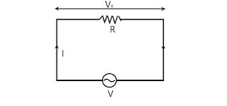
Let, the supply voltage of the circuit is, V=V0sin⍵t.
As there is no another element except the resistor R, so the voltage across R is also V, i.e. VR=V0sin⍵t. —-(1)
Now as per Ohm’s law,
V=IR
⇒I=V/R=V0sin⍵t/R
⇒I=I0sin⍵t [where, I0=V0/R] —–(2)
Where I0= Maximum current
From equation (1) &(2) we can clearly say that,
- Voltage and current are in the same phase. That means the phase difference,θ=0

- As the frequency, f=⍵/2𝜋 and as ⍵ is not changing, so that frequency is also the same.
Now as θ=0, therefore cosθ=1.
∴ Power consumed in the circuit, P= V0I0cosθ/2 = (V0I0)/2= {(V0)/√2}.{(I0)/√2}
∴ P= VrmsIrms.——(1)
Now,
Pure Inductive Circuit:
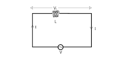
Let, the supply voltage of the circuit is, V=V0sin⍵t.
As there is no another element except the inductor L, so the voltage across L is also V, i.e. VL=V0sin⍵t. —-(1)
If the current I flow through the whole circuit, then the induced emf Ve= -L(dI/dt)
∴ V= V0sin⍵t-L(dI/dt) ——–(2)
Now as there is no resistance in the circuit, so R=0.
∴V=IR=0
⇒V0sin⍵t-L(dI/dt)=0
⇒V0sin⍵t=L(dI/dt)
⇒∫dI= (V0/L)∫sin⍵tdt
By integrating both sides we get,
I= (V0/L)(-cos⍵t/⍵)+k
=-(V0/⍵L)cos⍵t +k
[Here k is a time-independent constant. But in the voltage equation, there is no constant, which means the voltage oscillates symmetrically on both sides of the origin. So that the current generated in the circuit also oscillates symmetrically both sides of the origin. i.e. k=0]
∴ I=V0cos⍵t/⍵L [where I0=maximum current=V0/⍵L]
⇒I=I0sin(⍵-90°) ——(3)
From (1) &(3) we can easily say that,
Voltage and current are now not in the same phase. Now the phase difference,θ between them is 90°. That’s mean here the current is lagging behind the voltage by the phase difference of 90°.

Now as θ=90°, therefore cosθ=0.
∴ Power consumed in the circuit, P= V0I0cosθ/2=0
That’s mean in AC circuit if there is a pure inductor then no power will consume, that’s why this is called wattless current.
Next is-
Purely Capacitive circuit:
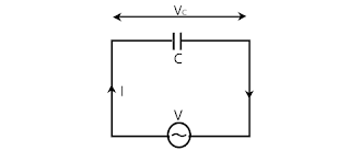
Let, the supply voltage of the circuit is, V=V0sin⍵t.
As there is no another element except the capacitor C, so the voltage across C is also V, i.e. VC=V0sin⍵t. —-(1)
Now if there is a charge Q in the capacitor, then it creates an inverse voltage Q/C.
∴ V= V0sin⍵t-Q/C ——-(2)
As in the circuit, there is no resistance, so
V=IR=0
⇒V0sin⍵t-Q/C =0
⇒V0sin⍵t=Q/C
By differentiating both sides,
⇒⍵V0cos⍵t=(1/C)dQ/dt=I/C [As I=dQ/dt]
⇒I=C⍵V0cos⍵t={V0/(1/⍵C)}sin(⍵t+90°)
⇒I=I0sin(⍵t+90°) —–(3)
Where maximum current, I0={V0/(1/⍵C)}
From (1) & (2) equation we can easily say that,
Voltage and current are now not in the same phase. But now current is no more lagged behind the voltage. Now the phase difference,θ between them is 90°. That’s mean here the current is leading the voltage by the phase difference of 90°.
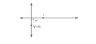
Now the great thing is here, in this case also, the current is wattless.
As θ=90°, therefore cosθ=0.
∴ Power consumed in the circuit, P= V0I0cosθ/2=0
That’s mean in the AC circuit if there is a pure conductor then no power will consume, which means the current is wattless.
Now let’s go to the –
LR Circuit:

Here, in this case
Let, the supply voltage of the circuit is, V=V0sin⍵t.(as usual) ———-(1)
But in this case, as we clearly see that here is an inductor and a resistor in the circuit. So what we can do? See-
If the current I flow through the whole circuit, then the induced emf Ve= -L(dI/dt)
∴ V= V0sin⍵t-L(dI/dt)
Now according to Ohm’s law,
V=IR
⇒ V0sin⍵t-L(dI/dt) =IR
⇒V0sin⍵t=L(dI/dt) +IR ——–(2)
Let, I=I0sin(⍵t+⍺)
∴ dI/dt = ⍵I0cos(⍵t+⍺)
Now putting the value of I and dI/dt, we get,
⇒V0sin⍵t = L⍵I0cos(⍵t+⍺) + I0Rsin(⍵t+⍺)
⇒ I0[L⍵cos(⍵t+⍺) + Rsin(⍵t+⍺)] = V0sin⍵t
Now let, Z=√{R2+(⍵L)2}[Z is called impudence, and ⍵L=XL is called the inductive reactance (see below)]
& tanθ = ⍵L/R
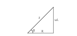
⇒ I0Z[⍵L/Zcos(⍵t+⍺) + R/Zsin(⍵t+⍺)] = V0sin⍵t
From the triangle, ⍵L/Z=sinθ and R/Z=cosθ, after substituting we get,
⇒ I0Z[sinθcos(⍵t+⍺) + cosθsin(⍵t+⍺)] = V0sin⍵t
⇒ I0Zsin(⍵t+⍺+θ) = V0sin⍵t
Comparing both sides we get,
⇒ ⍺+θ =0 ⇒ ⍺=-θ and I0Z=V0⇒ I0 =V0/Z =V0/√{R2+(⍵L)2}
∴I=I0sin(⍵t-θ)=V0/Z sin(⍵t-θ) ——(3)
From equation (1) and (3) this is clear that,
- No change occurs in the AC voltage and frequency of the current.
- The current I is lagging behind the voltage V with a phase difference θ. Where θ= tan-1( ⍵L/R)

- Whatever a resistance do in a purely resistive circuit, in this circuit the workfunction of Z is the same. Z is called the impedance of the AC circuit. The resistance against the current flowing in the LR circuit is the Impedance of the circuit to that alternating circuit.
∴ Power consumed in the circuit, P= V0I0cosθ/2 = (I0Z)I0(R/Z) x1/2 = (I0/√2)2*R
∴P=(Irms)2R ———-(4)
So, from equation (4) it is clear that in the LR circuit, no power is expended by the pure inductor L, all power is disrupted by the pure resistor R.
CR Circuit:

(As usual, we do)
Let, the supply voltage of the circuit is, V=V0sin⍵t. ———-(1)
Now if there is a charge Q in the capacitor, then it creates an inverse voltage Q/C.
∴ V= V0sin⍵t-Q/C
According to Ohm’s law,
V0sin⍵t-Q/C=IR
⇒ IR + Q/C = V0sin⍵t ———(2)
Suppose that, Q=Q0sin(⍵t+⍺)
∴ I=dQ/dt=⍵Q0cos(⍵t+⍺)
Putting the value in equation (2) we get,
⇒⍵RQ0cos(⍵t+⍺) + (Q0/C)sin(⍵t+⍺) = V0sin⍵t
⇒ ⍵Q0[ Rcos(⍵t+⍺) + 1/C)sin(⍵t+⍺)] = V0sin⍵t
By simplifying the equation,
⇒⍵Q0Zsin(⍵t+⍺-θ+90°) = V0sin⍵t [Here, Z=√{R2+(1/⍵C)2} and 1/⍵C =XC is called the conductive reactance]
By comparing both sides,
⇒ ⍺-θ+90°=0 ⇒⍺=θ-90°
& ⍵Q0Z= V0 ⇒ Q0 = V0/Z⍵
Now as I=⍵Q0cos(⍵t+⍺), we can simplify it. Let’s see what we’ve got after simplifying it,
I=⍵Q0cos(⍵t+⍺) = V0/Zcos(⍵t+θ-90°) = I0sin(⍵t+θ)
∴ I= I0sin(⍵t+θ) ——-(3)
Where, I0=V0/Z= V0/√{R2+(1/⍵C)2}
From equation (1) and (3) this is clear that,
- The current I is leading the voltage V by a phase difference θ. Where θ= tan-1( 1/⍵CR) {The diagrams are the same as the LR circuit.}
- And similarly, its power consumption is
P=(Irms)2R ———-(4)
If you like our site and think that it is a little bit helpful to you then subscribe to our newsletter to get regular updates.
-Thank u😊